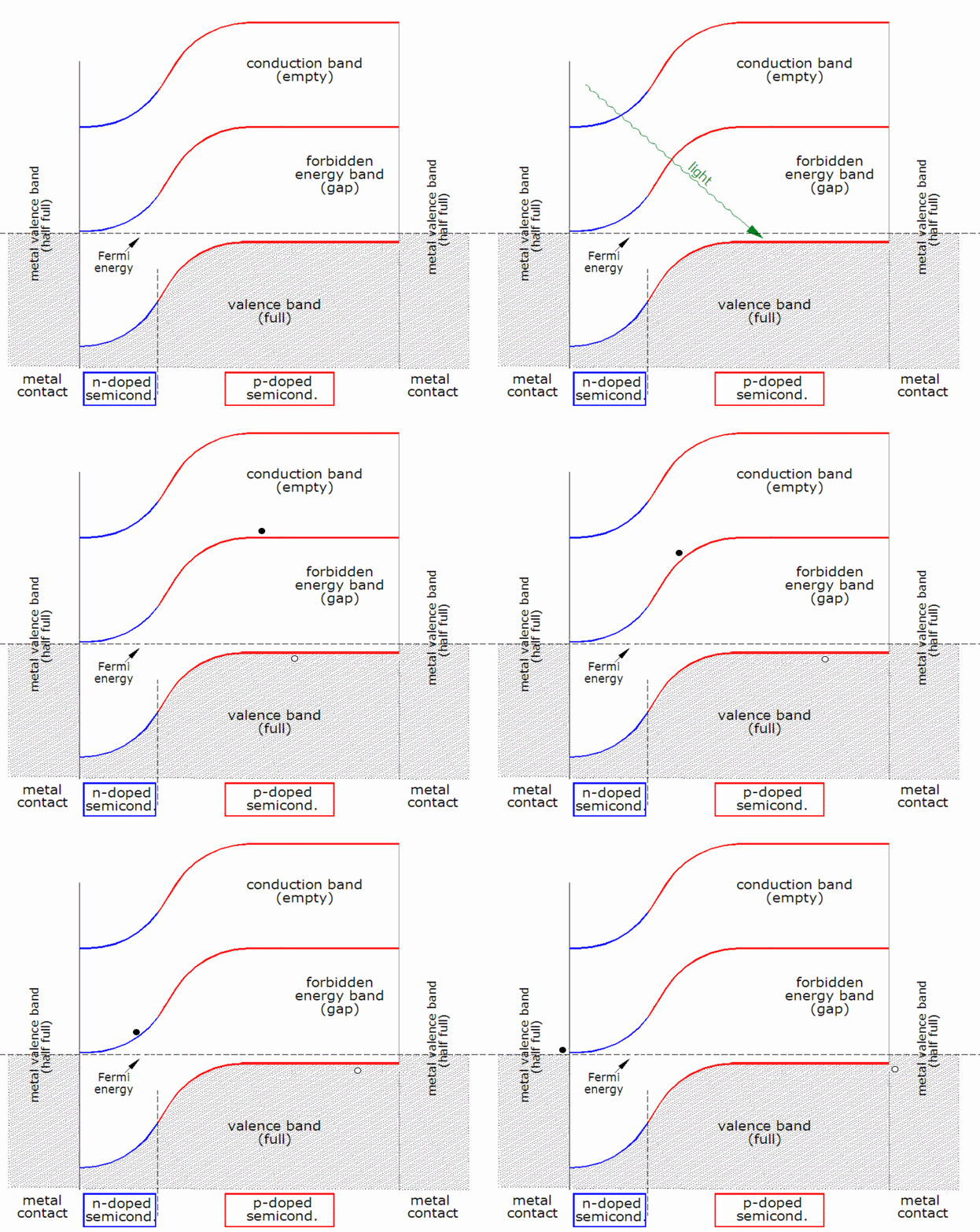
Here is a pictorial outlining DC Principles 101 every student learns in the 1st semester of school.

Electricity 4r Dummies & DIY
Collapse
This is a sticky topic.
X
X
-
Tags: None
- Stuck
-
Oooh perfect person to ask my question to then. In an ideal solar cell diagram there is a diode that is pointed towards the negative terminal in parallel and the solar cell is thought as a constant current source. Why is that diode there? It would seem to me that the diode in that configuration would just shunt all of the energy straight to the negative and you would be unable to use it for a load?
See equivalent circuit of a solar cell
-
A diode won't conduct at very low applied forward voltage. A shorted load connected to the solar cell will take all the available current,
but at zero volts takes no power. Increasing the load resistance slightly will generate some voltage drop and power transmitted to the
load. More resistance will give more voltage and at first more power, but as the voltage increases the diode starts conducting. A
point is reached where the power transmitted peaks; after that most of the current conducts internally and power delivered to the load
drops off again, zero at open circuit. Bruce RoeComment
-
Go to page http://www.pveducation.org/pvcdrom/s...ation/iv-curve
Look and click through on the example as they start with the simple cell, add light etc. You were not looking at a cell and a diode, you were looking solely at the PV diode. IL is just a representation of adding light and generating current, not adding a diode to a solar cell. enjoy and don't jump ahead to lessons before you understand the earlier lessons. That appears to be a great teaching site, but you need some electricity and electronics background to grasp the info they have there.Powerfab top of pole PV mount (2) | Listeroid 6/1 w/st5 gen head | XW6048 inverter/chgr | Iota 48V/15A charger | Morningstar 60A MPPT | 48V, 800A NiFe Battery (in series)| 15, Evergreen 205w "12V" PV array on pole | Midnight ePanel | Grundfos 10 SO5-9 with 3 wire Franklin Electric motor (1/2hp 240V 1ph ) on a timer for 3 hr noontime run - Runs off PV ||
|| Midnight Classic 200 | 10, Evergreen 200w in a 160VOC array ||
|| VEC1093 12V Charger | Maha C401 aa/aaa Charger | SureSine | Sunsaver MPPT 15A
solar: http://tinyurl.com/LMR-Solar
gen: http://tinyurl.com/LMR-ListerComment
-
Diodes only allow current to flow in 1 direction also called a rectifier. Turns AC into DC. Think of them as a 1-way valve for current to flow in one direction only.Last edited by Sunking; 07-31-2016, 08:27 PM.MSEE, PEComment
-
Comment
-
Great explanation. I wasn't even thinking about the forward voltage drop, and when I did think about the forward voltage drop I was thinking "gee, there's no way a solar panel would be effective with a forward diode dropping everything but .7 Volts" forgetting for a moment that they are made out of like 60+ cells and that's a cell diagram not a panel diagram. Now I understand why the MPPT systems are necessary.A diode won't conduct at very low applied forward voltage. A shorted load connected to the solar cell will take all the available current,
but at zero volts takes no power. Increasing the load resistance slightly will generate some voltage drop and power transmitted to the
load. More resistance will give more voltage and at first more power, but as the voltage increases the diode starts conducting. A
point is reached where the power transmitted peaks; after that most of the current conducts internally and power delivered to the load
drops off again, zero at open circuit. Bruce RoeComment
-
Would be possible to restore the image(s) on this thread/topic and some of the other stickies such as the "Ground Tutorial"? IMHO it would be hugely helpful to new readers coming through.
Also the links on the thread "Connecting to Earth" appear to be broken.
Apologies for posting on an old sticky but it seemed appropriate.
Comment
-
I looked at it briefly, and the pics at the source page seem to have moved. Perhaps Sunking will log back on and update it.Powerfab top of pole PV mount (2) | Listeroid 6/1 w/st5 gen head | XW6048 inverter/chgr | Iota 48V/15A charger | Morningstar 60A MPPT | 48V, 800A NiFe Battery (in series)| 15, Evergreen 205w "12V" PV array on pole | Midnight ePanel | Grundfos 10 SO5-9 with 3 wire Franklin Electric motor (1/2hp 240V 1ph ) on a timer for 3 hr noontime run - Runs off PV ||
|| Midnight Classic 200 | 10, Evergreen 200w in a 160VOC array ||
|| VEC1093 12V Charger | Maha C401 aa/aaa Charger | SureSine | Sunsaver MPPT 15A
solar: http://tinyurl.com/LMR-Solar
gen: http://tinyurl.com/LMR-ListerComment
-
The PVeducation link from laser411 seems to be up and showing the electrical model
for a PV cell. The Wikipedia link shows it as well. Bruce RoeComment


Comment